3D Vision
Up to now, the robot has been working with its eyes closed: positions come from teaching, workpieces are located by fixtures, and the slightest change in the environment leaves it flailing. To make a robot cope with a changing world, we have to give it eyes.
What machine vision is for
First, let's separate two terms. Computer Vision studies "understanding images"; machine vision in robotics has just one purpose: to give the robot the information it needs to manipulate an object. Around that purpose, it does three things:
- Object recognition: what's in the image;
- Pose estimation: the object's position and orientation in the camera frame — if the robot is going to grab it, knowing "what it is" isn't enough;
- Camera calibration: converting information from the camera frame into the robot frame — otherwise, no matter how accurately you see, the robot can't reach it.
Strung together, the three form a complete "see → locate → act" chain. This chapter won't survey vision algorithms — that's the job of a CV textbook; it answers just one question: to get this chain working, which pieces do you need to fill in, and where do you go to fill them? For the systematic camera models and multi-view geometry, see the two resources introduced in Advanced Practice: Penn's Robotics: Perception open course, and Peter Corke's textbook Robotics: Vision and Control.
Calibration: pin down the frames first
All the information a vision system gets is in the camera frame. To make it usable by the robot, you first have to pin down two layers of frames.
The first layer is the camera's own. The mainstream imaging model is the pinhole model — modern cameras use lenses, but geometrically they're equivalent to pinhole imaging: the spatial point, the optical center, and the image point are collinear. Projecting a 3D point to a pixel differs by an intrinsics matrix (focal length, principal point — depending only on the camera itself) plus a set of distortion coefficients; and the world frame to the camera frame is an extrinsic (look, SE(3) again). To back out these parameters from a calibration board of known dimensions, the methods basically all trace back to Zhengyou Zhang's classic paper[6] — and you don't have to implement it yourself: follow OpenCV's Camera Calibration tutorial, shoot about 20 photos of the board, extract the corners, and out come the intrinsics.
The second layer is the one between the camera and the robot — hand-eye calibration. A lab with no experience under its belt, trying to start 3D-vision research, often gets stuck right here, on step one. Camera mounting comes in two kinds: eye-to-hand (camera fixed relative to the base) and eye-in-hand (camera moves with the end-effector); the solution approach is the same. Take eye-to-hand as an example: fix a calibration board anywhere on the robot's end-effector, have the robot move through a few poses, and you have this coordinate loop:
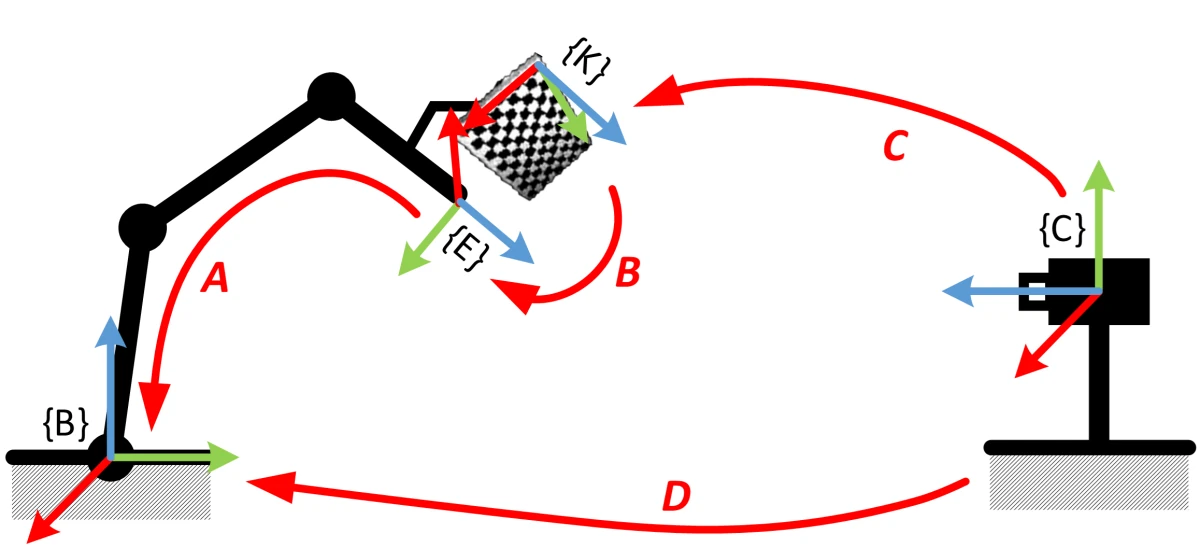
- A: the end-effector's pose in the base frame — forward kinematics, known;
- C: the camera's pose in the calibration-board frame — extrinsics, known;
- B: the board's pose on the end-effector — mounted arbitrarily, unknown, but fixed;
- D: the camera's pose in the robot base frame — this is what we want, and \(D = A \cdot B \cdot C\).
Have the robot move through two poses, use the fact that B is fixed to cancel it out, and you
get the classic \(AX = XB\) equation. Solving it is a standard drill — I've tried Tsai-Lenz,
Park-Martin, Horaud, and the dual-quaternion method; in most cases the accuracy is close, with

dual quaternion a touch better; OpenCV's calibrateHandEye implements them all. The eye-in-hand
case is perfectly symmetric: the board is fixed to the ground, the camera moves with the arm,
and you again cook up an \(AX = XB\). Paired with forward kinematics and extrinsics computation,
the whole process can be fully automated — the robot moves through the poses, takes the photos,
and does the math all by itself:
But let me add a caveat: every step above uses an "approximate model." Forward kinematics assumes the robot has no machining or assembly error (remember "calibration and identification" from the introductory part?), and the pinhole model is only an approximation of a lens system — the error at each link of the calibration chain multiplies into your final manipulation accuracy. When accuracy won't improve, look for the cause in these two directions; and the smarter approach is to not let the error accumulate at all — that's a setup for the demo later in this chapter.
Pose estimation: from templates to learning
With the frames sorted out, the next step is "where is the object." Depending on how troublesome the object is, the methods evolve step by step:
- Planar objects: the mainstream production-line scenario. Parts lie flat, needing only the three degrees of freedom \((x, y, \theta)\); edge extraction + shape matching is enough, and lighting plus a high-contrast background suppresses the variables — fast, accurate, stable, and many smart cameras have it built in;
- Textured objects: when lighting, distance, angle, and occlusion are all uncontrollable, rely on local feature points like SIFT[7] — they depend only on local texture and are insensitive to scale, rotation, and lighting. The feature points' 3D positions on the object are known when the library is built; match them online, solve a PnP, and you have the pose;
- Textureless objects: the many metal and plain-colored parts in industry, with no stable feature points to extract, bring us back to template matching — generate templates offline from multiple viewpoints (color gradient + surface normal, the representative algorithm being LineMod), localize coarsely online, then use ICP to finely register the model to the point cloud;
- Learning "where to grab" directly: in cluttered, piled-up bin picking, you often skip "what is it" and directly score candidate grasp poses on the point cloud.
For matching a real point cloud against a model point cloud, the keywords are ICP, NDT, and so on, all with ready-made implementations to reference in PCL.
What about deep learning? It has of course reshaped machine vision — but unevenly. Back when our lab studied the Amazon Picking Challenge (APC), this was what struck me most: the top-ranked teams had shifted object recognition almost entirely to deep networks, while pose estimation was still generally the traditional "segment the object's point cloud + ICP registration" routine. Recognition is where deep learning is strongest; pose is a regression problem, and a network's direct-regression accuracy isn't enough to support grasping, so the last step still needs a geometric method to back it up. Networks that directly regress pose have kept improving since, but the division of labor — "learn a coarse pose, refine it geometrically" — is still common in engineering.
Case study: visual servoing
The usual "look once → compute once → move with eyes closed" is an open-loop process: calibration error, pose-estimation error, and kinematics error all carry through, untouched, into the final accuracy — that's the price the "approximate model" warning was about. What if we close the loop? Vision continuously measures the relative pose between tool and target, the pose error (remember \(T_d \ominus T_c\) from Modern Robotics?) is fed straight to a PID, and the arm approaches the target continuously — the error is corrected by the next frame's observation before it's even finished. The errors along the chain no longer accumulate; accuracy depends only on "how accurately you can see." This is visual servoing.

With accurate enough vision and control, a robot can do work like threading a needle:
To study this direction systematically, the open-source library ViSP is a good project.
A few more notes
Many vision problems come from the complexity of the real world: lighting, object consistency, sensor stability, camera mounting angle, and more can all hand vision an "inexhaustible" supply of corner cases; without a well-drawn product boundary, vision problems are never fully solved.
As for SLAM — it really is part of robot vision too, but I'm not that familiar with it, so I'll just mention it briefly. It solves "where am I, and what does the map look like"; it's the perception backbone of mobile robots, a track running parallel to this chapter's "providing information for manipulation," and this book won't go into it. To get started, my top pick is Gao Xiang's 14 Lectures on Visual SLAM (in Chinese), which covers everything from the math foundations to programming practice; and you'll find its first few lectures are precisely about Lie groups and Lie algebras — different roads to the same place.